 Sprinkler Age A Publication of the American Fire Sprinkler Association
It’s Not Just About Four-Way Braces
When you think about seismic bracing for vertical sprinkler systems, your thoughts probably go straight to four-way bracing for risers. But there are several additional requirements that may come into play under the hanging and bracing requirements in NFPA 13, Standard for the Installation of Sprinkler Systems, for vertical sprinkler piping in certain cases. These requirements can affect the design and installation for drops to hose stations, rack sprinklers, or mezzanines as well as riser nipples and sprigs.
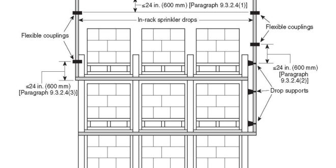
Section 9.3.2.4 of the 2016 edition of NFPA 13 requires that flexible couplings be installed on drops supplying hose lines, rack sprinklers, mezzanines, or other similar free-standing structures. It is important to note that the term “drop” used in this requirement is not intended to apply to a sprinkler drop to a single sprinkler. The purpose of the flexible coupling is to allow for some additional flexibility in the vertical piping connecting the overhead sprinkler system to piping fixed to a lower level structure that could move differentially during a seismic event. The flexible couplings are required, regardless of the diameter of the pipe that drops from the overhead system. Flexible couplings are required within 24 in. of the top of the drop, within 24 in. above the uppermost drop support attachment, and within 24 in. above the bottom of the drop if no additional drop supports are provided. (See Figure 1 above.)
The reader is told in section A.9.3.2.4 of the annex that he or she should evaluate the possible differential movement between the overhead piping system and a freestanding storage rack or other structure using the lesser value obtained from the following two formulas.
D = H x 0.06 x S1 x Fv
or
D = H x 0.05
Where:
D = the horizontal differential movement between the freestanding structure and the overhead system
H = the vertical height of the top point of attachment of the pipe drop to the freestanding structure
S1 = one second period spectral acceleration per USGS 2010 Seismic Design Maps (see SEI/ASCE7)
Fv = one second period site coefficient (Site Class D)
Before jumping into an example, let’s discuss a few details. The variable D is the amount of horizontal movement from the vertical (at rest) position of the rack. When determining the amount of movement afforded by a flexible coupling, there are several things to be aware of. First, the amount of deflection listed by manufacturers is for the total swing. So, for horizontal movement from vertical in one direction, only half of the available deflection is applicable. Second, the amount of movement depends on the type of groove. A cut groove allows for twice the amount of deflection of a rolled groove. Therefore, close attention should be paid to how each different manufacturer lists their maximum deflection values. Some list the values based on cut grooves while others’ values are based on rolled grooves. The diameter of the pipe also affects the amount of deflection. In general, larger diameter flexible couplings allow less deflection than smaller diameter couplings. For example, a 11/4-in. flexible coupling from one manufacturer allows 4 degrees of total deflection while the same manufacturer only allows 2 degrees for a 6-in. flexible coupling. A final point is that some manufacturers will provide a maximum possible amount of deflection on their product data tables with a footnote stating that only 25 percent to 50 percent of the deflection is to be used for design and installation purposes.
Let’s now move to an example. Assume for a moment that we have a building with a 46-ft ceiling height and 40-ft-high racks with in-rack sprinklers. The pipe drops from the overhead system to the in-rack sprinklers with 2-in diameter pipe. Assume that the drop is attached to the rack structure 5-ft below the top of the rack. Looking at several different flexible coupling manufacturers, we can see that the maximum angular deflection for a 2-in. flexible coupling ranges from approximately 1.5 to 3 degrees. For this example, we will assume the use of cut groove pipe, making it 3.0 degrees. Since we are evaluating movement from vertical in a single direction at a time, we must reduce the deflection to 1.5 degrees because the manufacturer’s data give total range of motion in both directions. This translates to a horizontal displacement of about 0.31 in. per one foot of vertical pipe. So, if we have a row of rack sprinklers beneath the top tier of storage this would likely equate to a 10-ft-long drop. The assumption is that the overhead system piping is at an elevation of 45 ft and the rack piping is at 35 ft. The amount of rack movement is calculated using the height at the point of attachment. It is important to observe that the longer the length of piping is between the flexible couplings and the point of attachment to the structure, the larger the horizontal deflection of the drop. In other words, if the distance between the couplings and the point of attachment is short, this will translate into a much smaller deflection than if the couplings are further away from the point of attachment. For this illustration, we will assume that there is a coupling at the top of the rack drop and each additional coupling will have a separation of 8 in. Remember that every coupling proceeding down the drop will provide less movement than previous couplings.
Calculation for Rack Displacement at Point of Attachment:
D = 35-ft rack x 0.05 = 1.75 ft of horizontal displacement = 21 in.
Calculation of Coupling Displacement:
Topmost Coupling:
• 1.50 deflection per cplg = 0.31 in. per 1 ft of drop x 10-ft drop = 3.1-in. deflection for topmost cplg
Second Coupling:
• 10 ft – 0.66 ft (8-in. lower) = 9.34 ft x 0.31 in./1 ft of drop = 2.9 in. of additional deflection
• Subsequent couplings will be 8-in. lower for every coupling thereafter, resulting in further reductions in horizontal displacement.
• Assuming there are a total of nine couplings the last coupling provides 1.5 in. of horizontal movement.
• The cumulative displacements should be added together to calculate the total allowable movement.
Total Deflection:
3.1 in. + 2.9 in. + 2.7 in. + 2.5 in. + 2.3 in. + 2.1 in. + 1.9 in. + 1.7 in. + 1.5 in. = 20.7 in.
This would mean that we could need as many as nine or 10 flexible couplings in the drop to the top row of rack sprinklers, with the lowest coupling being 5.33-ft below the topmost coupling. If you have rolled grooves, you can fill the entire 10-ft drop with 16 couplings and only have 13.6 in. of movement. This is still well short of the recommended 21 in. Even with cut grooves, if you apply the recommended 50 percent reduction for design, you only have 13.6 in. of movement; still not enough.
It is important to clarify that, other than the couplings required in section 9.3.2.4, the additional couplings on the drop to a rack or similar structure and the calculations of the displacement of the same structure are all printed in the Annex. Therefore, these are not currently requirements by the standard. So, meeting the minimum requirements for flexible couplings in the standard could, in many cases result in an installation that falls well short of the recommended flexibility in movement to prevent the drop piping from potentially being damaged during an earthquake.
Let’s now move to the next item. When riser nipples are utilized in a system that requires seismic bracing, the stress placed on the riser nipples by seismic forces must be evaluated unless one of the following conditions is met:
• The riser nipples are 4 ft or less in length and Cp is 0.50 or less.
• The riser nipples are 3 ft or less in length and Cp is less than 0.67.
• The riser nipples are 2 ft in length or less and Cp is less than 1.0.
If one of the three conditions is not met then the stresses that would be placed on the riser nipples during an earthquake must be calculated to verify that the allowable yield strength of the riser nipples would not be exceeded. The following formula is used to evaluate the stress on the riser nipples:
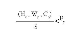 Where:
• Hr= length of the riser nipple (in.)
• Wp= tributary weight (pounds) for the branch line or portion of branch line in the zone of influence for the riser nipple
• Cp = seismic coefficient
• S = section modulus of the riser nipple
• Fy = allowable yield strength of the riser nipple material (30 ksi for steel or copper, 8 ksi for CPVC)
If the calculation determines that the actual stress on the riser nipple exceeds the allowable yield strength then longitudinal seismic bracing must be provided for the branch line that is fed by that riser nipple. Longitudinal seismic loads on the branch line are calculated and used to size the longitudinal brace(s) for the branch line. Note that the above equation has been corrected. The equation shown in section 9.3.5.9.6.1 of the 2016 edition of NFPA 13 incorrectly states that the calculated value of the stress on the riser nipple should be greater than or equal to the allowable yield strength.
One final item to cover is sprigs. As mentioned previously in this article, drops to individual sprinklers, regardless of length, do not require flexible couplings. Sprinkler drops, as well as armovers, are also exempt from the requirements for restraint. Sprigs, however, if 4 ft in length or more, are required to be restrained. The restraint of long sprigs is required because, while gravity will help to maintain drops in a general downward orientation, sprigs will tend to roll downward during seismic activity. This can be even more pronounced in installations where grooved branch lines are used. Sprigs should be restrained using restraining wire or other approved means.
In conclusion, while much of the focus on seismic protection for sprinklers systems is placed on the main piping and risers, the aforementioned requirements for drops and riser nipples should not be ignored. After all, any system is only as robust as its weakest part. The failure of a sprinkler system caused by the shearing off of a 2-in. rack drop during a seismic event would be more than enough damage to completely cripple the system.
 ABOUT THE AUTHOR: Parks Moore is the chief executive officer of S & S Sprinkler Company in Mobile, Alabama. He has a bachelor’s degree in mechanical engineering from Vanderbilt University and a master’s in business administration from Tulane University. Parks is a licensed fire protection engineer, a Certified Fire Protection Specialist and holds a NICET IV certification in water-based systems layout. He currently serves as an alternate member on the NFPA 13 Technical Committee for Installation, principal member of the NFPA 15 Technical Committee for Water Spray Fixed Systems, and formerly served as a member on the NFPA 13 Technical Committee for Hanging and Bracing. He is a past president of the Alabama Fire Sprinkler Association and has been actively involved as one of its board members since 2007. Moore is also a member of AFSA, NFPA, and SFPE.
IMPORTANT NOTICE: The article and its content is not a Formal Interpretation issued pursuant to NFPA Regulations. Any opinion expressed is the personal opinion of the author and presenter and does not necessarily present the official position of the NFPA and its Technical Committee.