 Sprinkler Age A Publication of the American Fire Sprinkler Association

Significant Changes Coming in 2016 NFPA 13
If you’ve ever installed or designed a system with a fire pump or a header then you’ve probably used pipe stands in some form or fashion. But how did you know how to design the pipe stands? Sure, there have been several manufactured pipe stands on the market for years. These usually consist of 1-1⁄2-in. or 2-in. Schedule 40 pipe with some sort of saddle or u-bolt and base plate. But there are also more than a few shop-made and field-fabricated pipe stands supporting headers and fire pump piping across the country.
Prior to the 2007 edition of NFPA 13, Standard for the Installation of Sprinkler Systems, there was no direct mention of pipe stands in this standard. Two lines were inserted in the 2007 edition regarding design requirements for pipe stands. These two lines merely required that they must be designed to support five times the weight of the water-filled pipe plus 250 pounds and that they must be approved where they are used. Note that the standard says that pipe stands must be approved, but it does not say that they shall be listed.
Jump ahead two cycles to the 2013 edition and you will find that not much has changed. One additional passage was added in 2013 requiring that pipe stands must be secured by an approved method. In short, both the pipe stand and the method for securing the pipe stand base shall be approved. Depending on the expectations of the Authority Having Jurisdiction (AHJ), this could result in the requirement for an engineer to design the pipe stands on your project.

If you have ever worked for a company that designs or installs water spray fixed systems then you may be familiar with the use of pipe stands on an entirely different level. Such systems are designed in accordance with NFPA 15, Standard for Water Spray Fixed Systems for Fire Protection. Water spray fixed systems often require the use of overhead piping outside and in the open without the presence of overhead structure to hang piping from. As a result, such systems may rely on the use of pipe stands to support much or all of the system piping.
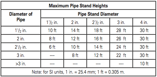
NFPA 15 has long allowed for the use of what has been known as self-supporting piping systems. But it too was lacking in guidance pertaining to pipe stands until the standard underwent a major reorganization in 2001. During that development cycle, significant guidance was added, including a pipe stand spacing table, guidance on types of materials from which the pipe stands were to be constructed, and a maximum height table based on the size of the stand and the size of the system piping. (See Table 1.) The installation guidelines were based on the assumption that pipe stands would be connected to a looped piping network. This is an important factor, which will be discussed in more detail later in this article. Since the modifications to the 2001 edition, the NFPA 15 pipe stand requirements have remained unchanged for the last 15 years.
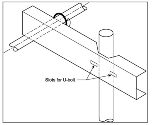
Since NFPA 13 covers overall hanging and bracing requirements for all water-based fire protections standards for NFPA, the Hanging and Bracing Committee for NFPA 13 formed a task group to study pipe stands and propose any changes needed for the 2016 edition. The work that came out of the task group, along with input from the technical committee resulted in the addition of substantial new language that will be included in the 2016 edition of NFPA 13. The new language will provide guidance on sizing of pipe stands, material construction, anchoring and base plate requirements, and sizing for horizontal support arms. (See Figure 1.)
The adopted language still allows professional engineers to design their own pipe stands as long as they meet the five design stipulations, as has been allowed by the hanging and bracing requirements of previous versions of NFPA 13. Pipe diameters of up to 10 inches will be allowed to be supported by a 2-in. Schedule 40 pipe stand as long as the pipe stand height is not over 4 ft tall, as measured from the centerline of the supported pipe to the base of the pipe stand, and the pipe stand is under axial load only. (Figure 2.) Supports taller than 4 feet or eccentrically supported stands must be sized using the new tables.
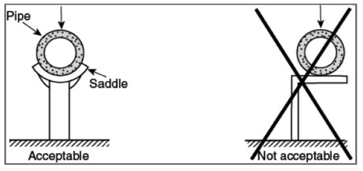
Table 2 shows the sizing table and allowable stand heights that will be included in the 2016 edition of NFPA 13. If you compare this to Table 1, it is evident that there are two major differences. The new NFPA 13 table has included a column allowing for the use of 6-in. diameter pipe stands, and the allowable heights for a given size stand are lower in NFPA 13 than they are in NFPA 15. The reasoning for this was alluded to earlier in this article. Supported piping designed in accordance with NFPA 15 is assumed to be looped together. This creates additional rigidity to the top of the pipe stands. The hanging and bracing committee limited the slenderness ratio (KL/R) to 300 when they calculated the allowable heights given in Table 2. The K value for a column that is rigidly braced on both ends is 1.0, while the K value for a cantilevered column supported only at its base is 2.1. This means that, when evaluating the allowable maximum heights based on slenderness ratio, a pipe stand that is rigidly braced on both ends could be more than twice as long as one that is fixed only at its base. Since system piping installed in accordance with NFPA 13 is not assumed to be looped, a K value of 2.1 was used to determine the allowable heights.
The heights in Table 2 are also based on the sprinkler pipe being attached to the pipe stand through the use of a horizontal support arm similar to the one shown in Figure 1. The length of such support arms will be limited to a maximum of one foot, as measured from the center line of the pipe stand to the center line of the system piping that is being supported. This length was chosen to control the stresses in the column, the support arm, and the fasteners to a reasonable level. While the slenderness ratio was the height limiting factor on the larger diameter stands, the bending stresses induced by the eccentric loading from the support arm were found to be the height limiting factor for the smaller diameter stands. (See Table 2.)
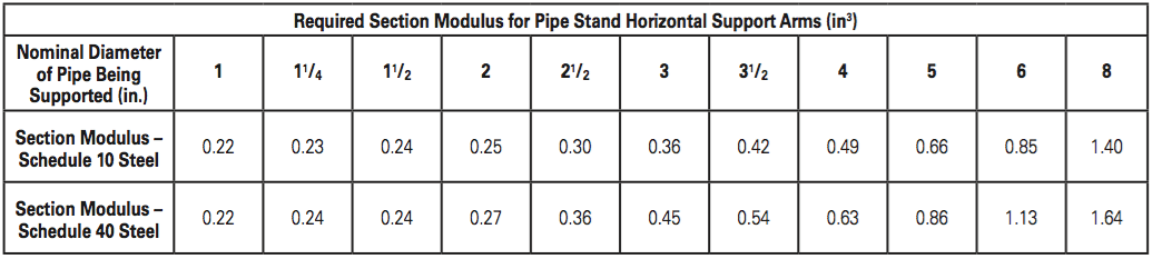
Table 3 above provides the necessary moduli required to adequately size the horizontal support arms. Sizing is based on the diameter and schedule of the system piping that is being supported. It is assumed that the maximum allowable length of one foot is being used. Once the required modulus is determined, the appropriate support arm size can be chosen using the section modulus table for commonly available shapes for trapeze hangers in NFPA 13.
As a result of these changes to NFPA 13, the NFPA 15 technical committee has also formed a task group to evaluate modifications to the language on pipe stands in its standard. There will likely be proposed changes that will add guidance for horizontal support arms to that standard, as well as modifications to the allowable heights as a result of further analysis on the bending stresses caused by the eccentric loading from these support arms.
IMPORTANT NOTICE: As a member of the NFPA 13 and 15 tech- nical committees, the following disclaimer applies. The article and its content is not a Formal Interpretation issued pursuant to NFPA regulations. Any opinion expressed is the personal opinion of the author and presenter and does not necessarily represent the of- ficial position of the NFPA and its technical committee.
 ABOUT THE AUTHOR: Parks Moore is the Chief Executive Officer of S & S Sprinkler Company in Mobile, Ala. He has a bachelor’s degree in mechanical engineering from Vanderbilt University and a master’s in business administration from Tulane University. Parks is a licensed fire protection engineer, a Certified Fire Protection Specialist and holds a NICET IV certification in water-based systems layout. He currently serves as an alternate member on the NFPA 13 Technical Committee for Hanging and Bracing and is a principal member of the NFPA 15 Technical Committee for Water Spray Fixed Systems. He is a past president of the Alabama Fire Sprinkler Association and has been actively involved as one of its board members since 2007. Moore is also a member of AFSA, NFPA, and SFPE.