 Sprinkler Age A Publication of the American Fire Sprinkler Association

The Importance of
Henderson Engineers has performed multiple forensic investigations that identified installations that do not comply with NFPA 13 requirements as the root cause that led to pipe failures and subsequent property damage. If these installation inconsistencies are not identified during the initial inspection and commissioning processes, it’s unlikely that they will be corrected prior to a system malfunction.
Installation Standards Matter NFPA 13 establishes the minimum standards for the design and installation of dry pipe systems. No two systems are exactly the same due variable factors like building construction, occupancy, contents, and physical location. One of the most challenging – and most important – aspects of installing dry pipe systems is ensuring the sprinkler piping has the proper pitch. As a consulting engineer, we review many contractor submittals that state the piping will be pitched to the riser or auxiliary drain in accordance with NFPA 13. Of course, installing pipe in the field is a more challenging task than adding a plan note.
Case Study Case in point, our firm was recently retained by an owner’s insurance company to survey their facility fitted with a dry pipe sprinkler system that protected an unconditioned attic and a conditioned area below the ceiling. The sprinkler system had been plagued with issues throughout the building’s life. Pinhole leaks and oxygen corrosion developed shortly after the building opened, requiring system piping to be partially replaced. A nitrogen generator was recommended and installed by the service contractor to address the corrosion issues and reduce the number of leaks. These were all valid suggestions by well-meaning service contractors. Unfortunately, despite these attempted remedies the corrosion and leaks continued for several years because the root cause of the problem was not addressed. Our analysis identified large portions of the system that were improperly pitched causing large amounts of water to be trapped in the system. Ultimately the system froze, resulting in a broken pipe and water damage loss claim costing the building owner’s insurer thousands of dollars in damages in addition to temporary loss of the damaged portion of the facility.
Installation Parameters are Clear Parameters for proper dry pipe pitch are clearly established in NFPA 13. In a correct installation, the water in the pipe drains completely after system tests or activation prior to putting the system back in service. During installation, the pipe should be pitched to drain toward either the water source (such as a dry pipe valve) or another designated drain valve called an auxiliary drain. If the pipe is not pitched, or worse yet, is pitched in the wrong direction, water will be trapped in the pipe permanently. Trapped water can result in internal corrosion and subsequent pinhole leaks and/or fractured pipes (caused by expansion and contraction due to freezing and thawing).
NFPA 13 8.16.2.3 provides direction on how much slope is required for dry pipe installations: ¼ in. per 10 linear feet of pipe for mains and ½ in. per 10 linear feet for branch lines. Translating into degrees of slope defined as:
During our case study, a forensic examination of the damaged piping confirmed our initial hypothesis: the dry pipe sprinkler system did have water trapped in the pipe due to errors in installation. The trapped water likely contributed to several of the system’s issues throughout its life.
The overall finding was the system had not been installed in accordance with the designated pitch in the approved plans and NFPA 13, and the inconsistencies were not identified during acceptance inspections and commissioning. Subsequently, system components were replaced without addressing the pipe pitch errors, perpetuating the problem. Interestingly, the root cause of the issue may have been a simple spirit level.
The Accuracy Conundrum During a sprinkler system’s installation, accuracy is paramount. Correctly verifying NFPA 13’s relatively small slope requirement is critical to confirm compliance in order to mitigate the aforementioned issues. Several instruments are available, including spirit levels, digital levels, and machinist’s levels, to assist contractors.
The most economical tools on the market for level measurement are spirit (or bubble) levels. While inexpensive, these levels should only be used to confirm that a pipe is level (0° relative to flat) or plumb (90° relative to flat). They should not be used to determine proper pipe slope on installed pipe. An old rule of thumb states “1/4 bubble outside the line indicates proper pitch” – but that may not be correct! An installer needs accurate slope measurements to verify compliance with NFPA 13.
A second level measurement technology is the digital level or inclinometer. These levels display the measured slope via a numerical display, typically in degrees of slope to the tenth of a degree, similar to the display shown in Figure 1.
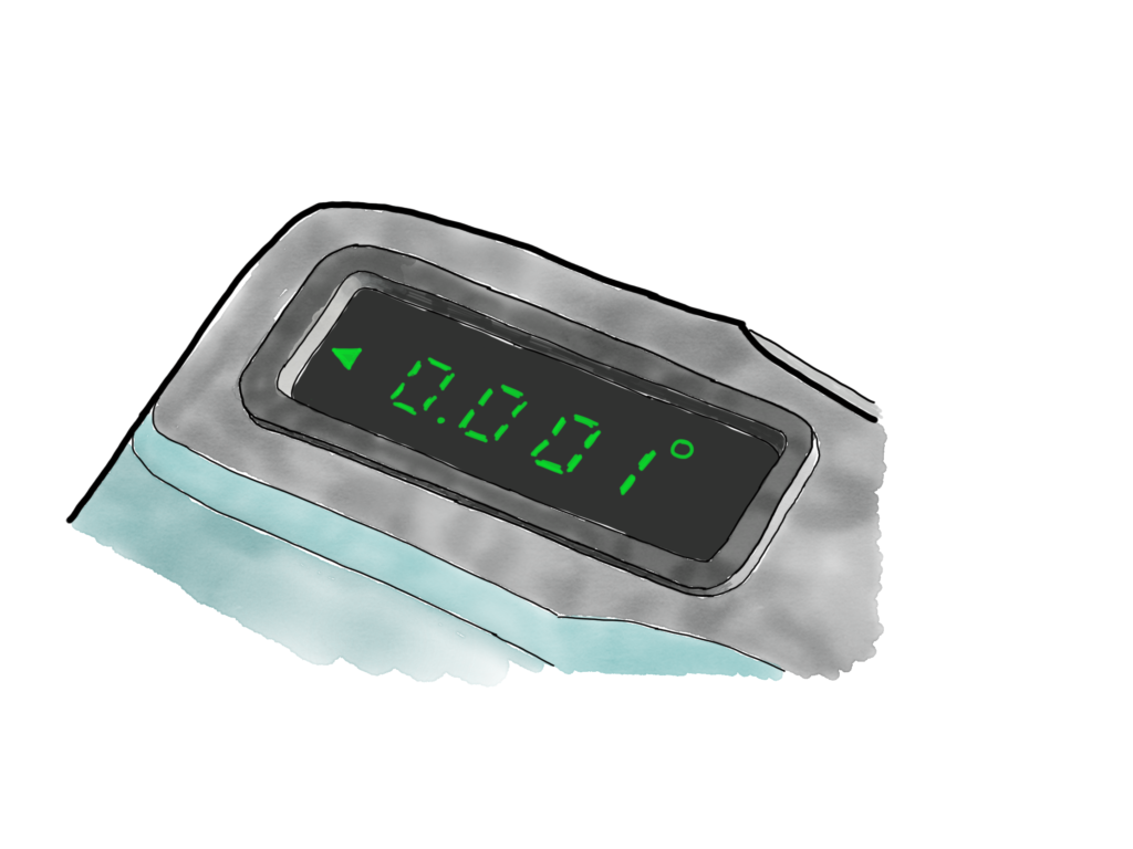
Figure 2. A machinist’s level with a display resolution to 0.001°.
This digital display implies that the scale is accurate to within 0.1° of level. A review of several levels on the market indicates an absolute error of ±0.1° up to 1.0° of slope. That’s a fine accuracy for framing a house, but let’s determine what the level will display when placed on the minimum code-compliant pitch for fire sprinkler main piping:
• Minimum Range Reading: Minimum Slope Required – Accuracy
• 0.119° – 0.1° = 0.019° Low Range
• Because the value is less than 0.05° the display will read 0.0°
In other words, even though the installation is compliant, the digital level reads as if it is not. This is a high-quality tool but it has inherent limitations. The level’s combination of accuracy and display resolution are inadequate to report a properly minimally-pitched main piping.
Another tool, the spirit-based machinist level, provides much more accuracy than a typical digital level. This level has graduations equivalent to 0.005 in./ft or 0.024°. Determining the low-range value for a spirit-based machinist’s level:
• Minimum Range Reading: 0.119° – 0.024° = 0.095°
Like the digital level, the minimum range reading could result in several correctly installed systems registering as non-compliant. However, the installer can consider this possibility and may allow for some leeway in the slope measurement due to the inherent error in the device.
Fortunately, several tools are available that will provide the required resolution and accuracy to confirm adequate slope. For installers who prefer the ease of reading digital displays, several digital machinist’s levels are available that will yield acceptable results. For example, one machinist’s level has a display resolution to 0.001° and an absolute error of ±0.002° from 0° to ±0.5° (±0.004° at other angles), similar to the illustration in Figure 2.
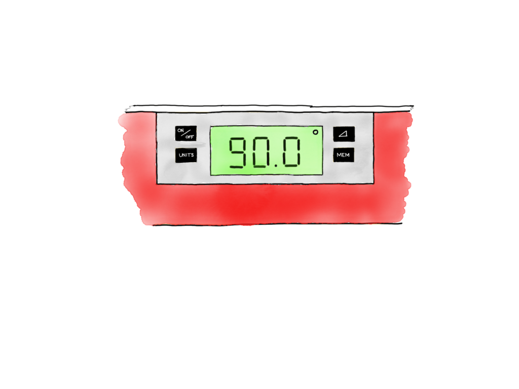
Figure 1. A digital level or inclinometer displays the measured slope to the tenth of a degree.
This accuracy results in the following display range on the low side:
• Minimum Range Reading: 0.119° – 0.002° = 0.117°
This level provides the installer a much more accurate reading than the other measurement tools to confirm code compliance. Note that some machinist’s levels are not capable of measuring a slope greater than 2° so a lower resolution level still has a role in the contractor’s toolbox.
Summary A properly designed and installed suppression system that adheres to NFPA 13 significantly improves the occupants’ chance of surviving a fire. Installers may benefit from the use of more accurate measuring tools to minimize their financial exposure after projects have been installed. A loss, like the one discussed above, can indicate that established design parameters and maintenance guidelines were not adhered to. Documenting that an installation complies with national standards can protect the contractor from losses due to water leaks, inadvertent system activations, and damage because of environmental factors.
In either case, the many variables required to design, inspect, and maintain an adequate, reliable suppression system must be considered. As was documented in the case study, the improper pitch of system piping cost the owner and their insurance provider thousands of dollars and months of unusable space in their facility. Many times, the difference between proper performance and unnecessary loss is simply a matter of small details.
ABOUT THE AUTHORS: Christopher Culp is vice president and director of fire protection engineering for Henderson Engineers. He helps manage Henderson’s fire- and life-safety team and has 21-plus years of experience in the design of fire protection systems and building code compliance. He has served as a principal for the fire and life safety group since 2007.
Bob Renton is a senior code consultant and Henderson’s director of forensic engineering. Renton spent more than 25 years in the fire service industry, including roles as fire captain, investigator, and code analyst.