 Sprinkler Age A Publication of the American Fire Sprinkler Association

Weighing the Differences
For most sprinkler projects the building structure is of sufficient design and capacity to allow hanging of sprinkler components directly to the structure. Structural engineers take into account loads imposed on the structure by the sprinkler system and calculate them into the building design. Safety factors are applied to ensure adequate capacity is provided.
However, there are times, whether it be in a new construction or a retrofit in an existing building, that maximum concentrated loads and/or uniform loads will not permit direct hanging to structural elements. Mains, or even branchlines, can introduce unanticipated excessive loads to beams, trusses, purlins, joists, etc. The structural engineer identifies the maximum permitted uniform loads and concentrated loads used in the structural design. The sprinkler system contractor should always check the specifications and/or consult with the structural engineer for the load limitations prior to laying out the sprinkler system. Hanger placement, quantity, and locations may have to be adjusted to be within load limitations.
Chapter 9 of NFPA 13, Standard for the Installation of Sprinkler Systems, provides requirements for hanging and bracing. The building structure integrity must be capable of supporting the weight of the water filled pipe plus 250 pounds, with some exceptions. What NFPA 13 does not indicate, is the length of the water filled pipe that must be used in the load calculation. Although, there are maximum spacing requirements between hangers for each pipe type which ultimately limits the maximum possible point loads for sprinkler piping. The industry standard is to use the midpoint of the span between two hangers when calculating pipe lengths and point loads. However, there is an equation in the Annex for trapeze hangers to adjust the equivalent length if the applied load is off center, see Figure 2.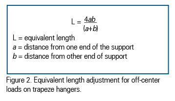
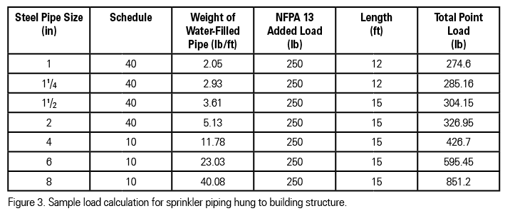
Figure 3 is an example of a load calculation for sprinkler piping connected to the building structure. Of course, if hangers were spaced closer together, the point loads would decrease. Armovers, drops/sprigs, sprinklers, and valves would have to be added to total load to complete the point load calculations, as necessary.
Of note, while the structure is only required to support the weight of the water filled pipe plus 250 pounds, the hangers themselves must be designed to support five times the weight of the water filled pipe plus 250 pounds.
 So what happens when the sprinkler system imposes a load that cannot be supported by the building structure? One of the first options (if the building structure has the capacity) is to transfer the loads across two structural members by using a trapeze hanger which in turn reduces the point load at each attachment. NFPA 13 has provided a few tables in Chapter 9 to assist in sizing the trapeze hangers. Interestingly, the calculations were performed using the weight of the water filled pipe plus 250 pounds. The calculations do not include the safety factor of five times that is required for hangers.
When trapeze hangers are provided, either by the sprinkler contractor or another trade, the idea to share trapeze hangers is often contemplated, see Figure 1. Prior to the 2013 edition of NFPA 13, there was one attempt to allow sprinkler piping installed below ductwork to share supports with the ductwork, otherwise no allowance had been provided for hanging non-sprinkler components from the same support structure as the sprinkler components, unless it was the building structure itself. Sprinkler piping had to be supported independently using hangers and trapezes dedicated to fire sprinkler systems.
- 9.1.1.7 Support of Non-System Components. Sprinkler piping or hangers shall not be used to support non-system components. [2010 edition]. The 2013 edition finally permitted the sharing of sprinkler hanger supports with other building systems.
- 9.1.1.8.2 Sprinkler piping shall be permitted to utilize shared support structures in accordance with 9.1.1.3. [2013 edition]
- In addition to being required to be certified by a registered professional engineer and the requirements of 9.1.1.2, NFPA 13 requires shared support structures to meet one of the following:
- 9.1.1.3.1.1 Sprinkler pipe and other distribution systems shall be permitted to be supported from a shared support structure designed to support five times the weight of water filled sprinkler pipe and other supported distribution systems plus 250 lb (114 kg), based on the allowable ultimate stress.
- 9.1.1.3.1.2 Sprinkler pipe and other distribution systems shall be permitted to be supported from a shared support structure designed to support five times the weight of the water filled sprinkler pipe plus 250 lb (114 kg), and one and one-half times the weight of all other supported distribution systems.
Figure 4 is an example of the same pipes and same spacing of the sprinkler piping used in Figure 3, except it is connected to a shared support structure. Also note, the total point loads of any shared distribution systems are not included.
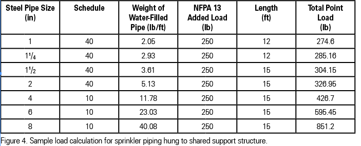 One can see, for the same piping, the required point loads are a lot heavier when connected to a shared support structure than those connected to the building structure. One may ask, why does NFPA 13 require a safety factor on the pipe of five times for shared support structures, but not on building structure? Shouldn’t the safety factor be the same? Why is there a difference?
The difference is in the way structural engineers analyze building structure components. Chapter 16 of the International Building Code (IBC) provides the basic requirements of structural members. Load effects on structural members take into account an overall analysis of how the structural system transfers loads from the point of origin through the load bearing elements to the foundation. As part of the analysis, various load combinations and associated safety factors are applied. Most loads are calculated using assigned, average expected uniform loads (e.g., 50 pounds per square foot live load, etc.) unless specific framing characteristics or loads require modeling differently. The load combinations are calculated using up to 22 equations with combinations of dead and live loads which include environmental loads such as rain, snow and wind. Each of these loads carry their own safety factors ranging from 0.5 to 1.6. These safety factors are additive in the equations. The combinations also take into account the probability of what level of loads will occur in combinations with others.
For a shared support, load shedding through distributed framing is no longer valid. The accuracy of the applied load also becomes more critical as these loads are typically applied as point loads versus distributed loads and the consequences of underestimating the loads can be catastrophic. The NFPA 13 committee has realized this and required a 5.0 safety factor plus 250 pounds to ensure the sprinkler system is secure when connected to shared support structures. They have also required an increase of 50 percent of the other loads to reflect potential variations in the assumed load characteristics. The 250 pounds is the anticipated load of an installer if he/she has to hang onto the pipe in an emergency.
ABOUT THE AUTHOR: Duane Johnson, P.E. is design manager with Strickland Fire Protection, College Park, Maryland. He is a graduate from the University of Maryland Fire Protection Engineering program.
IMPORTANT NOTICE: The article and its content is not a Formal Interpretation issued pursuant to NFPA Regulations. Any opinion expressed is the personal opinion of the author and presenter and does not necessarily present the official position of the NFPA and its Technical Committee.